A wind turbine (also referred to as a wind generator, wind machine, or wind engine) is a device that converts the kinetic energy of airflow into mechanical energy; it is an essential component of a wind power plant. This device is typically coupled to an electric generator. The wind turbine harnesses wind power to drive a rotor—most commonly a three-bladed design—into rotation; a gearbox then steps up this rotational speed to drive the generator and produce electricity.
A wind turbine consists of a nacelle (head), a yaw mechanism, and a tail fin. The nacelle captures the wind energy and converts it into electrical energy, while the tail fin ensures the turbine remains constantly aligned with the direction of the incoming wind to maximize energy capture. The yaw mechanism allows the nacelle to rotate flexibly, thereby enabling the tail fin to effectively adjust the turbine's orientation. Within the nacelle, the rotor features permanent magnets, and the stator windings cut through the magnetic flux lines to generate electricity.
Compared to other power generation methods—such as solar, hydroelectric, geothermal, thermal (coal-fired), and gas-fired power—wind power offers relatively low greenhouse gas emissions, minimal water consumption requirements, and positive social impacts.
Wind turbine components—particularly wind turbine rotors—must be designed for lightweight construction while simultaneously ensuring structural integrity and long-term performance stability. Furthermore, to meet economic imperatives, these components must also offer cost-effectiveness. Moreover, the extended production cycles involved necessitate the use of materials that possess a dual combination of high-temperature resistance and ease of processing.
The evolution of wind turbine rotors has progressed from early materials such as wood, metal, and engineering plastics to the current widespread use of Glass Fiber Reinforced Plastics (GFRP). In this context, GFRP components are fabricated by impregnating glass fibers or carbon fibers—of varying lengths—with polymeric matrices, typically epoxy or unsaturated resins. The exterior surfaces may be further reinforced by filament winding with glass fibers and coated with epoxy resin, while the interior sections are filled with structural foam.
Within this composite structure, the primary functions of the foam core are to enhance stiffness, improve structural stability, and reduce overall mass. The intrinsic mechanical properties of the foam directly influence the mechanical performance of the entire sandwich structure; concurrently, variations in foam density affect the mass distribution of the component, which in turn influences its load distribution characteristics. Polyvinyl Chloride (PVC) foam is currently the most widely utilized material in this category; classified as a thermoset foam, it was also the first structural foam core material to be adopted in the sandwich structures of load-bearing components. However, thermoset foams—exemplified by PVC—present environmental and resource-related challenges due to their non-degradable and non-recyclable nature. Consequently, as the global economy transitions toward a low-carbon future, thermoplastic foams—such as PET (Airex)—are expected to garner increasing attention and undergo significant development.
Types
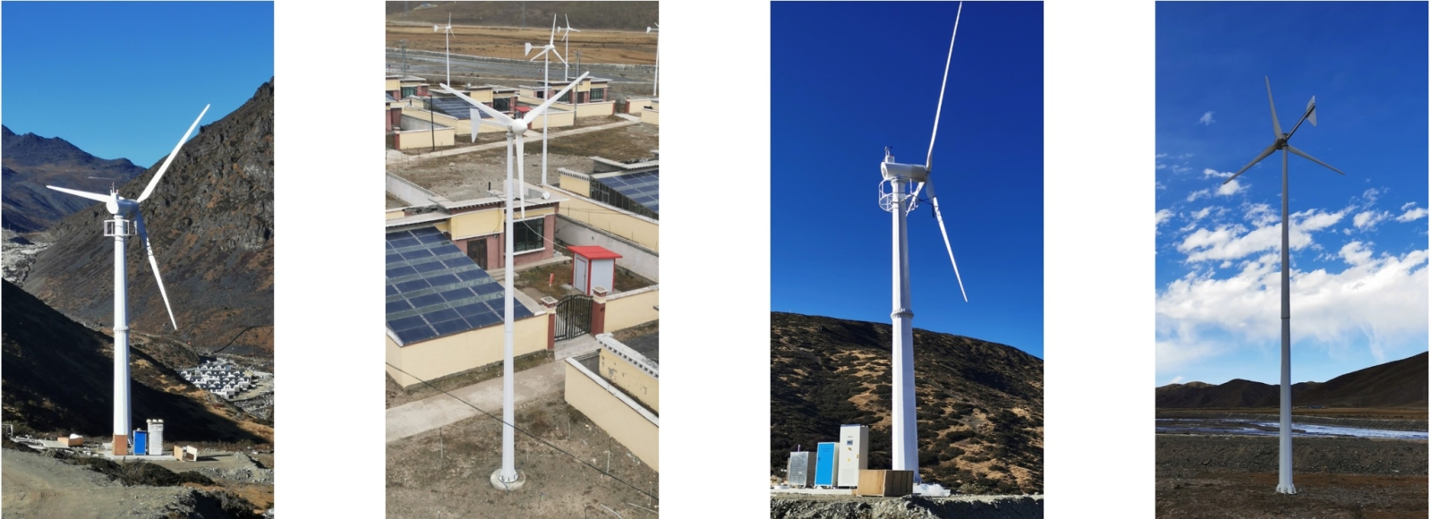
Horizontal-Axis Wind Turbines
Horizontal-axis wind turbines are equipped with a yawing mechanism that allows them to rotate in response to changes in wind direction. For small-scale wind turbines, this mechanism typically utilizes a tail vane; for large-scale turbines, however, it employs a drive system comprising wind direction sensors and servo motors. The rotor of the wind turbine is mounted on a hub; when the turbine is in operation, if the hub faces directly into the wind, it is classified as an "upwind" turbine; conversely, if it faces away from the wind, it is classified as a "downwind" turbine. Horizontal-axis wind turbines come in a wide variety of designs: some feature counter-rotating rotors; others mount multiple rotors on a single tower to reduce structural costs while maintaining a specific power output; and some designs generate vortices around the rotor to concentrate the airflow and increase wind velocity.
Vertical-Axis Wind Turbines
Vertical-axis wind turbines can be broadly categorized into two types: lift-driven and drag-driven. Lift-driven turbines rotate at high speeds, whereas drag-driven turbines rotate at slower speeds. For practical wind power generation applications, lift-driven vertical-axis turbines are predominantly utilized. A significant advantage of vertical-axis wind turbines—particularly when compared to their horizontal-axis counterparts—is that they do not require a yawing mechanism to orient themselves toward the wind when the wind direction changes. This feature not only simplifies the structural design but also minimizes the gyroscopic forces exerted on the rotor during wind direction shifts.
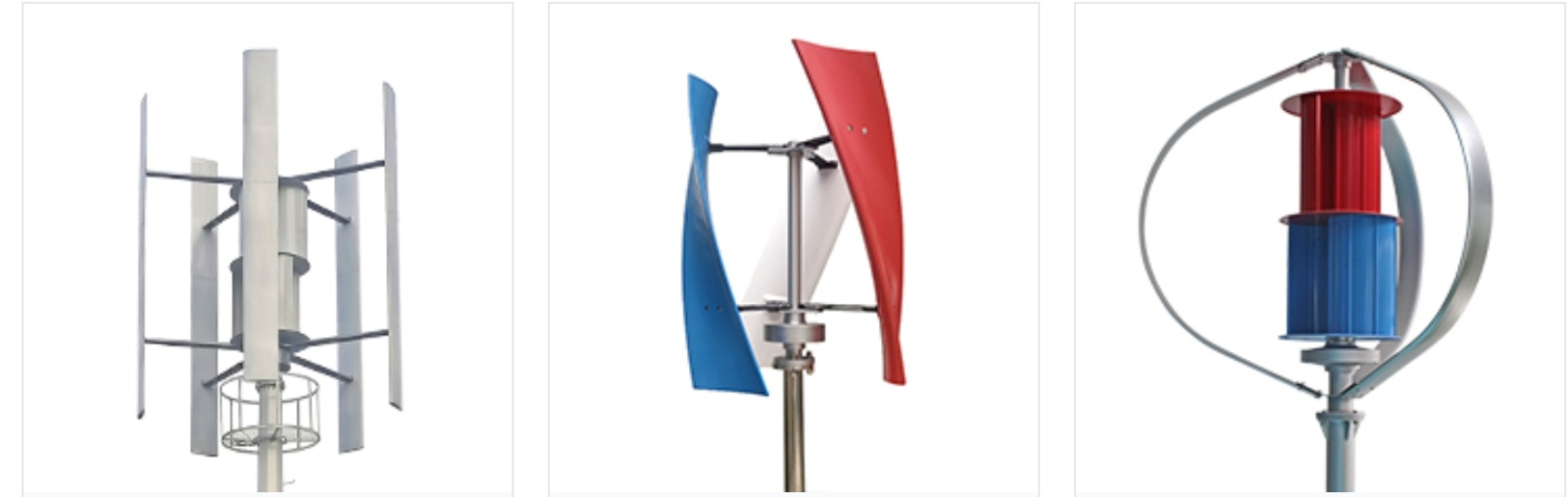
There are several types of vertical-axis wind turbines that operate based on drag forces. These include designs featuring rotors constructed from flat plates or cup-shaped vanes—devices that function purely on the principle of drag—as well as S-shaped rotors, which generate some lift but remain primarily drag-driven devices. While these systems possess high starting torque, they exhibit a low tip-speed ratio; consequently, given a fixed rotor size, weight, and cost, they yield a lower power output compared to lift-driven designs.